RTK Positioning
Introduction to Real-Time Kinematic (RTK) Positioning, and Ublox Neo-M8P series.
RTK Positioning
即時動態定位技術: 利用衛星達到即時精準定位的一種技術,方式為同時在參考站與移動站接 收衛星資料,透過通訊設備,將參考站的觀測資料傳送給移動站,移動站再透過差分計算,可以在移動時即時獲得精確的定位坐標。
Real-time kinematic positioning (RTK) is the application of surveying to correct for common errors in current satellite navigation (GNSS) systems. It uses measurements of the phase of the signal’s carrier wave in addition to the information content of the signal and relies on a single reference station or interpolated virtual station to provide real-time corrections, providing up to centimetre-level accuracy.
Introduction to Network RTK
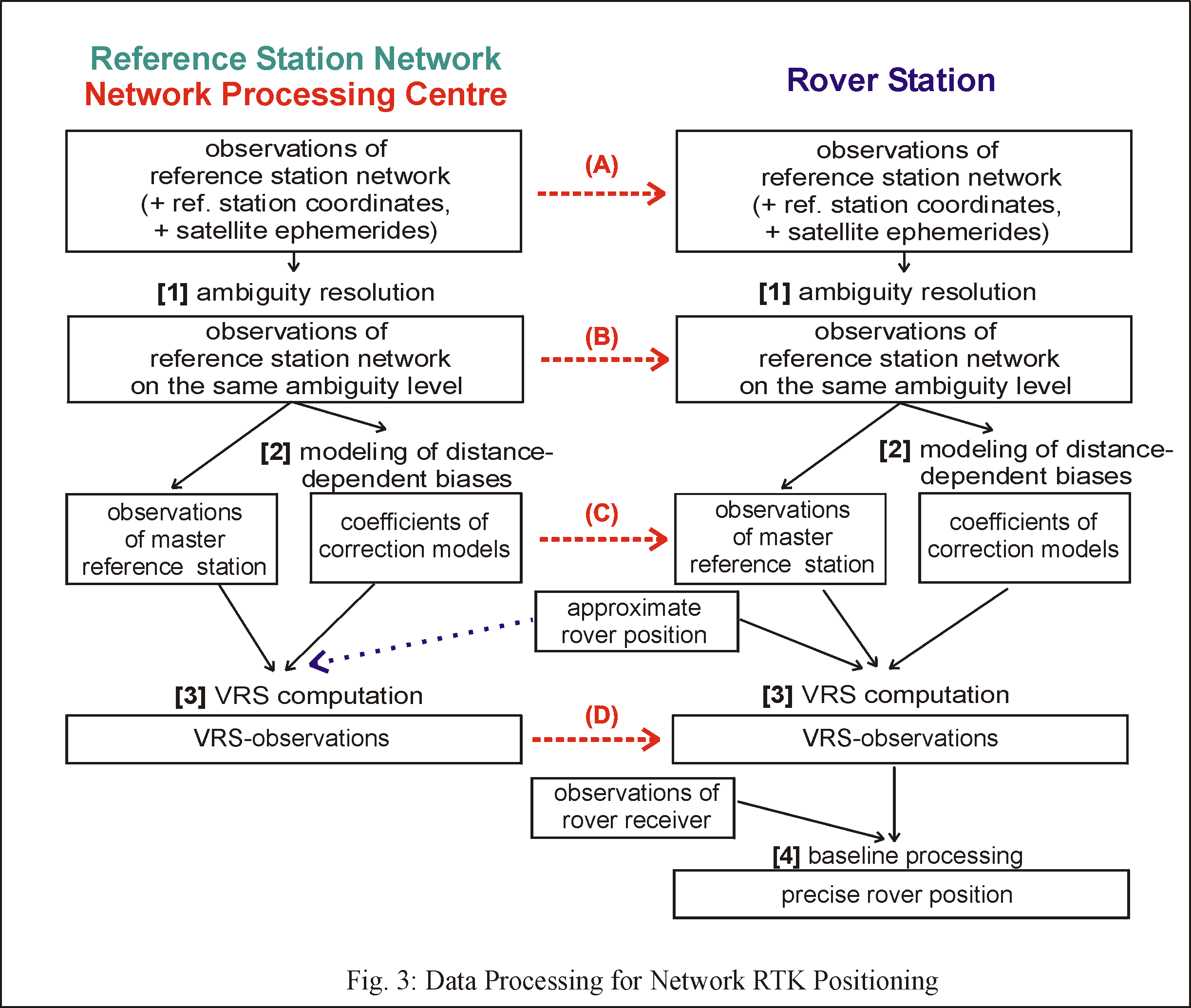
Paper: Network Real Time Kinematic (NRTK) Positioning – Description, Architectures and Performances
Ublox
NEO-M8P series
 u-blox M8 high precision GNSS modules
- NEO-M8P-0 : u-blox M8 high precision module with rover functionality
- NEO-M8P-2 : u-blox M8 high precision module with rover and base station functionality
- NEO-M8P Product Summary
- NEO-M8P Data Sheet
- NEO-M8P Hardware Integration Manual
AppBoards
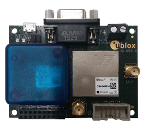
- C94-M8P AppBoard : u-blox RTK application board package
- Drotek RTK GNSS modules

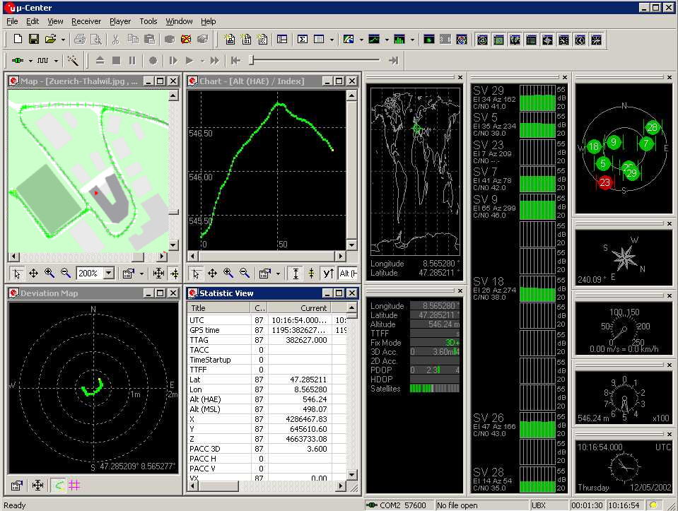
u-center
GNSS evaluation software for Windows
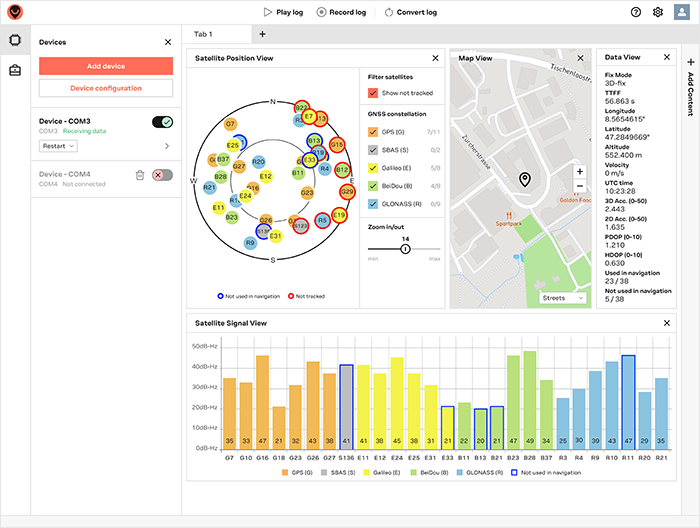
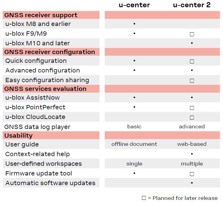
- For M10 products only : u-center 2, User Guide
- For M9 products and below: U-Center v22.05, User Guide
Set up Ublox Base and Rover Devices
Blog: Autonomous Agri-robot Control System
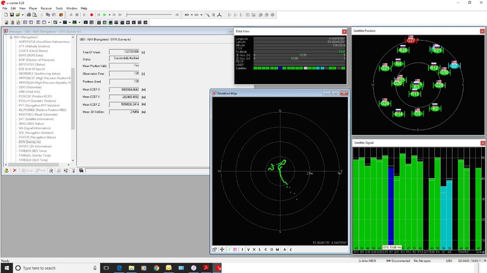
- For an initial test, use the quick 2 minute ‘survey in’ file: Ublox_Base_20minutes.txt
- For accurate, repeatable, results use the 24 hour version - be warned - it takes 24 hours before you can use the devices! : Ublox Base 20hours.txt
- The Rover uses the same config file whatever: Ublox Rover.txt
RTK M8P Positioning Solutions
- Drotek RTK GNSS modules using NEO-M8P
- Configuring the base manually
- Configuring the rover manually
- The Telemetry system (MAVLink)

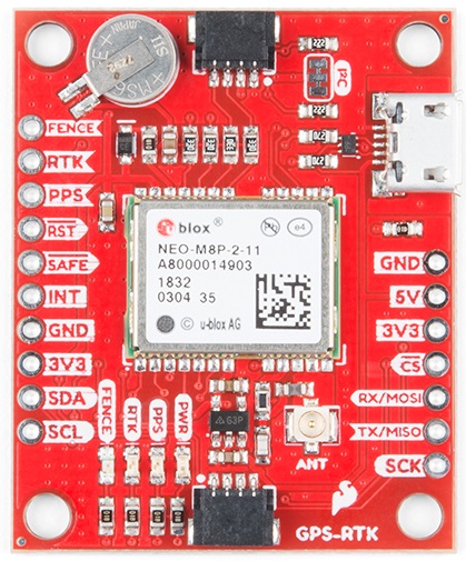
SparkFun GPS-RTK board - NEO-M8P-2
- SparkFun Ublox Arduino Library
- Example1: Read NMEA sentences over I2C using u-blox module SAM-M8Q, NEO-M8P, etc
- Example2: Parse NMEA sentences using MicroNMEA library. This example also demonstrates how to overwrite the processNMEA function so that you can direct the incoming NMEA characters from the u-blox module to any library, display, radio, etc that you prefer.
- Example3: Get latitude, longitude, altitude, and satellites in view (SIV). This example also demonstrates how to turn off NMEA messages being sent out of the I2C port. You’ll still see NMEA on UART1 and USB, but not on I2C. Using only UBX binary messages helps reduce I2C traffic and is a much lighter weight protocol.
- Example4: Displays what type of a fix you have the two most common being none and a full 3D fix. This sketch also shows how to find out if you have an RTK fix and what type (floating vs. fixed).
- Example5: Shows how to get the current speed, heading, and dilution of precision.
- Example6: Demonstrates how to increase the output rate from the default 1 per second to many per second; up to 30Hz on some modules!
- Example7: Older modules like the SAM-M8Q utilize an older protocol (version 18) whereas the newer modules like the ZED-F9P depricate some commands using the latest protocol (version 27). This sketch shows how to query the module to get the protocol version.
- Example8: u-blox modules use I2C address 0x42 but this is configurable via software. This sketch will allow you to change the module’s I2C address.
- Example9: Altitude is not a simple measurement. This sketch shows how to get both the ellipsoid based altitude and the MSL (mean sea level) based altitude readings.
- Example10: Sometimes you just need to do a hard reset of the hardware. This sketch shows how to set your u-blox module back to factory default settings.
- NEO-M8P: Examples specific for the NEO-M8P.
- NEO-M8P Example1: Send UBX binary commands to enable RTCM sentences on U-blox NEO-M8P-2 module. This example is one of the steps required to setup the NEO-M8P as a base station. For more information have a look at the u-blox manual for setting up an RTK link.
- NEO-M8P Example2: This example extends the previous example sending all the commands to the NEO-M8P-2 to have it operate as a base. Additionally the processRTCM function is exposed. This allows the user to overwrite the function to direct the RTCM bytes to whatever connection the user would like (radio, serial, etc).
- NEO-M8P Example3: This is the same example as NEO-M8P’s Example2. However, the data is sent to a serial LCD via I2C.
- ZED-F9P: Examples specific for the ZED-F9P.
- ZED-F9P Example1: This module is capable of high precision solutions. This sketch shows how to inspect the accuracy of the solution. It’s fun to watch our location accuracy drop into the millimeter scale.
- ZED-F9P Example2: The ZED-F9P uses a new u-blox configuration system of VALGET/VALSET/VALDEL. This sketch demonstrates the basics of these methods.
- ZED-F9P Example3: Setting up the ZED-F9P as a base station and outputting RTCM data.
- ZED-F9P Example4: This is the same example as ZED-F9P’s Example3. However, the data is sent to a serial LCD via I2C.
- There are only three steps to initiating a base station:
- Enable Survey-In mode for 5 minutes (300 seconds)
- Enable RTCM output messages
- Begin transmitting the RTCM packets over the backhaul of choice
- If you have a ‘rover’ in the field in need of correction data you’ll need to get the RTCM bytes to the rover. The SparkFun u-blox library automatically detects the difference between NMEA sentences and RTCM data. The processRTCM() function allows you to ‘pipe’ just the RTCM correction data to the channel of your choice. Once the base station has completed the survey and has the RTCM messages enabled, your custom processRTCM() function can pass each byte to any number of channels:
- A wireless system such as LoRa or Cellular
- Posting the bytes over the internet using WiFi or wired ethernet over an Ntrip caster
- Over a wired solution such as RS485
- The power of the processRTCM() function is that it doesn’t care; it presents the user with the incoming byte and is agnostic about the back channel.
- EMLID NTRIP CASTER: Pass corrections between your RTK GNSS receivers over the Internet
Ardupilot - Here+ RTK GPS
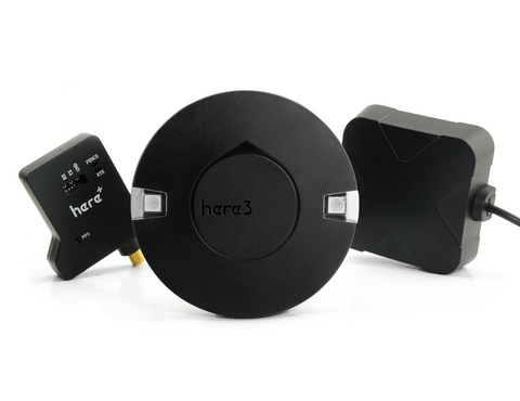
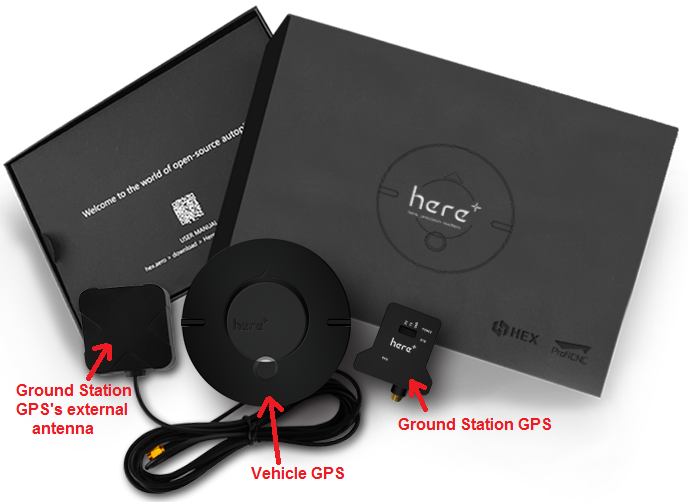 Here 3 & Here+ RTK Base (M8P) Combo
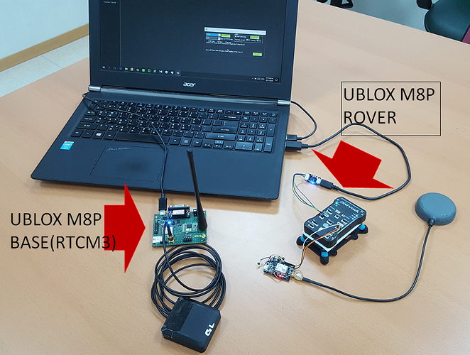
Integration of ublox M8P RTK in Ardupilot
Bad GPS reception
Kalman Filter
This site was last updated October 07, 2024.
