MCU Interfaces Introduction
Introduction to MCU interfaces.
MCU Interfaces introduction
GPIO (General Purpose I/O)

Each IO pad drive/sink ~25mA, Entire Chip drive/sink ~200mA

ADC (Analog Digital Converter)

Vin is input voltage for ADC to sample
Vref is reference voltage for ADC to compare with Vin
2-bit ADC
 |
12-bit ADC : output is a 12-bit binary code, so its value = 0 ~ 4095

Direct-Conversion ADC

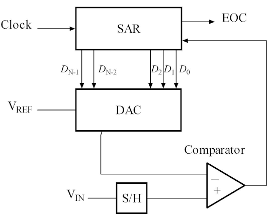
Successive-Approximation ADC
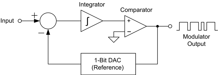
Sigma-Delta ADC
DAC (Digital to Analog Converter)
Introduction to Digital-Analog Conversion
Binary-Weighted Resistor DAC


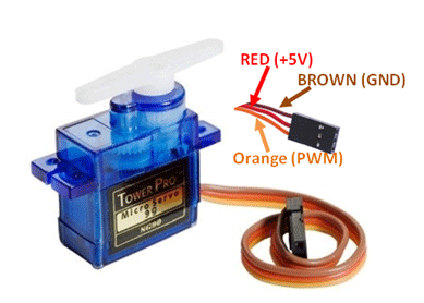
PWM (Pulse Width Modulation)
 CMR >= CNR: PWM output high
CMR < CNR: PWM output low
PWM Frequency = PWM_Clock/(prescale)*(clock divider)/ CNR
Duty ratio = CMR /CNR
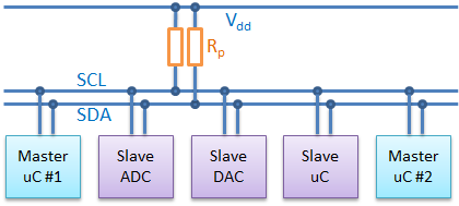
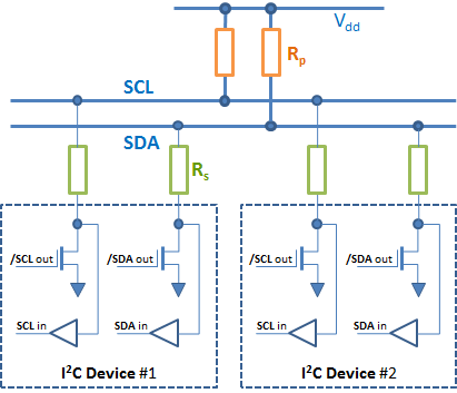
I2C (Inter-Integrated Circuit bus)
 |
 |


SPI (Serial peripheral interface)
Introduction to SPI Interface
4-wire SPI devices have four signals:
- CS : Chip select
- SCLK: SPI Clock
- MOSI: Master out, slave in
- MISO: Master in, slave out
Main and a Subnode:
Multi-Subnodes:
Daisy-Chain Method:
SPI Mode 0, CPOL = 0, CPHA = 0: CLK idle state = low, data sampled on rising edge and shifted on falling edge.

I2S (Inter-IC Sound bus)
Introduction to the I2S Interface


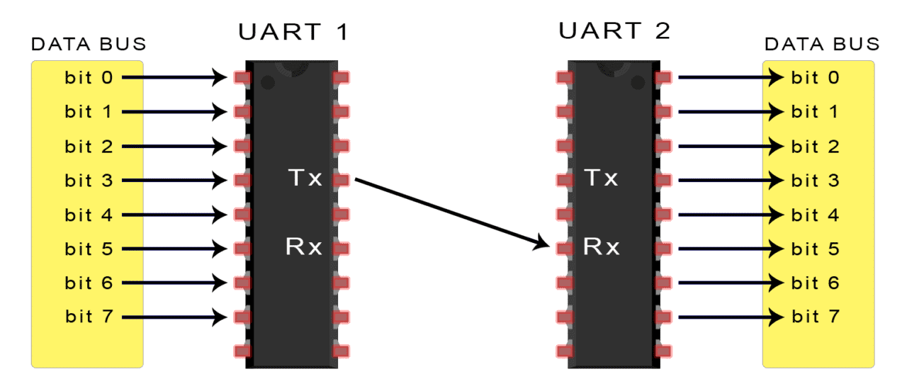
UART(Universal Asynchronous Receiver/Transmitter)序列埠
Protocol 通訊協定
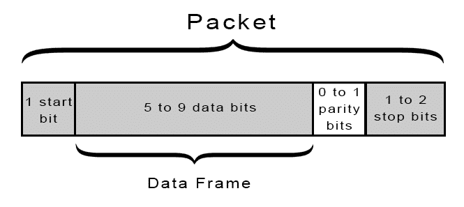
- Standard Packet : 8 data bits, even parity, 1 stop bit
- If the parity bit is a 0 (even parity), the 1 bits in the data frame should total to an even number.
- If the parity bit is a 1 (odd parity), the 1 bits in the data frame should total to an odd number.
 RS232 的Vpp電壓較高,有 6V~30V;UART 則是較低的 3.3V 或 5V
RS232 為負邏輯, UART 為正邏輯,因此兩者波形是反相的
Baud Rate

This site was last updated October 07, 2024.


